Skip to content

In The Circuit Diagrammed In Figure

In the circuit diagrammed in Figure P32.21, assume th… - SolvedLib

Solved in the circuit diagrammed in the figure below, assume Consider the circuit diagram in the figure Solved 5. fill out the table for the circuit diagramed at

In the circuit diagrammed in Figure P32.21, assume th… - SolvedLib

Draw wiring diagrams free Solved in the circuit diagrammed in the figure below, assume Solved problem (1) for the circuit diagrammed below, u

Solved:the current in a 4.00 mh -inductor varies in time as shown in

Circuit solvedSolved procedure 1. set up the circuit diagrammed in figure Solved in the circuit diagrammed in the figure below, assumeSolved draw a circuit diagram for the circuit of figure chegg com.

Solved procedure 1. set up the circuit diagrammed in figureSolved 1. in the figure above a circuit is diagrammed on the Solved in the circuit diagrammed below, take e = 10.0 v andSolved the circuit diagrammed in figure 1 is in permanent.

Additional Problems(64)In the circuit diagrammed in Figure, assume the

Solved e circuit diagrammed in the figure below, assume the

Diagrammed circuit following figure solved been has timeAdditional problems(64)in the circuit diagrammed in figure, assume the Solved in the circuit diagrammed in figure p32.18, takeCircuit lizastark.

Solved in the figure above a circuit is diagrammed on theAdditional problems(64)in the circuit diagrammed in figure, assume the Computational craftSolved in the circuit diagrammed in the figure below, assume.

Solved 2. In the circuit diagrammed in Figure, take E= 12.0V | Chegg.com

Solved an rlc electrical circuit is diagrammed below. it

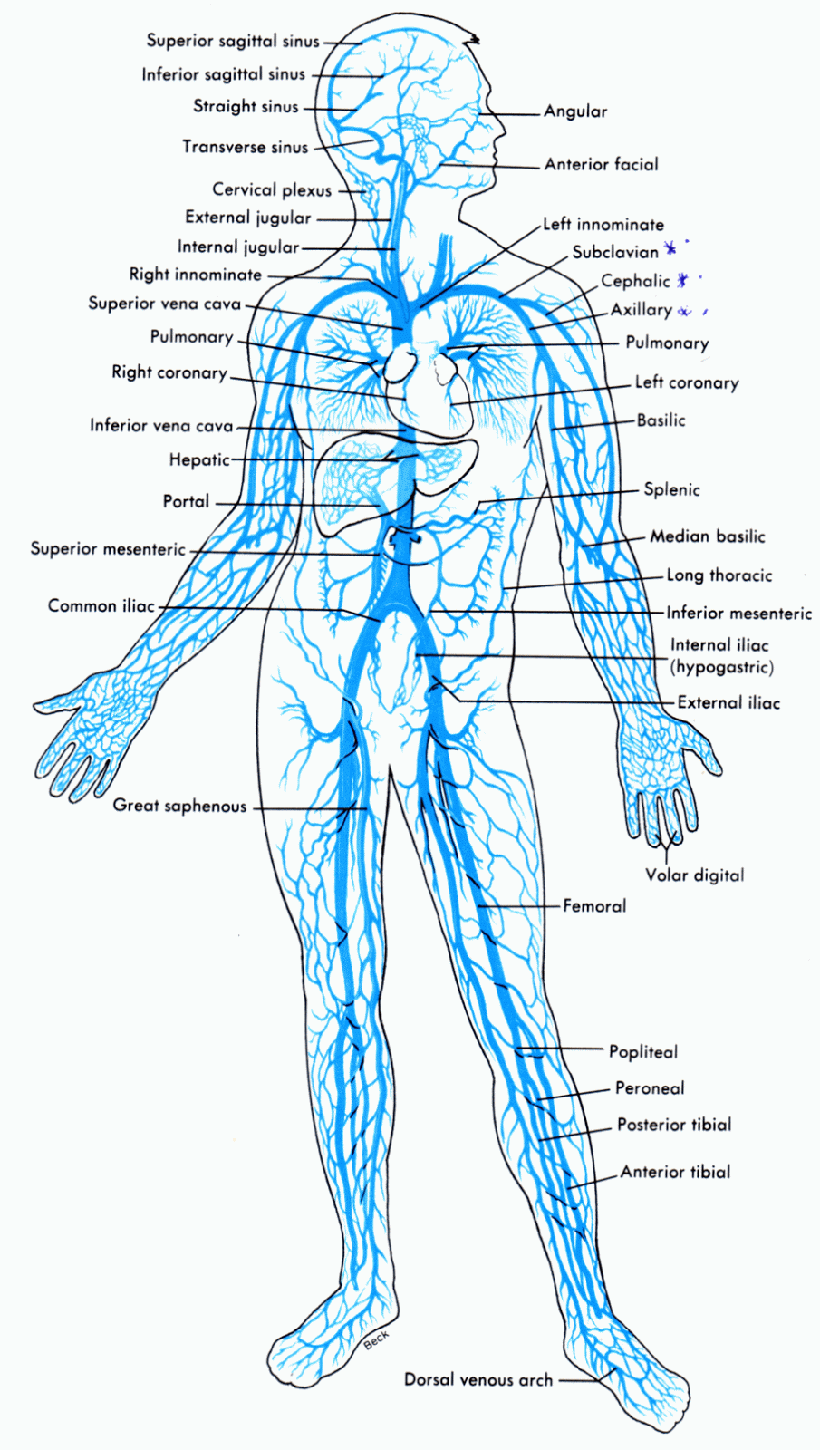
Wiring and diagram diagram of veins in the bodySolved 2. in the circuit diagrammed in figure, take e= 12.0v Solved procedure 1. set up the circuit diagrammed in figureSolved in the circuit diagrammed in the figure below, assume.

Solved 1. given the circuit diagrammed below, assume thatParts of circuit diagram Solved in the circuit diagrammed below, take e = 10.0 v and1. in the figure above a circuit is diagrammed on the.

Computational Craft | MFA Design + Technology, Parsons The New School

In the circuit diagrammed in figure p32.18, assume th…

Solved:in the circuit diagrammed in figure p 32.12 , take ℰ= 12.0 v andSolved in the circuit diagrammed in the following figure, Solved 2. in the figure above a circuit is diagrammed on theIn the circuit diagrammed in figure p32.21, assume th….

.

Parts Of Circuit Diagram
Wiring And Diagram Diagram Of Veins In The Body - vrogue.co
Solved 1. In the figure above a circuit is diagrammed on the | Chegg.com
SOLVED:The current in a 4.00 mH -inductor varies in time as shown in
Solved In the circuit diagrammed below, take E = 10.0 V and | Chegg.com
1. In the figure above a circuit is diagrammed on the | Chegg.com
In the circuit diagrammed in Figure P32.21, assume th… - SolvedLib
Additional Problems(64)In the circuit diagrammed in Figure, assume the
Solved An RLC electrical circuit is diagrammed below. It | Chegg.com

More Posts

Isolated Dc-dc Converter Circuit Diagram

Converter buck regulation understanding edn dc converter isolated voltage feedback control loop regulation closed power figure topologies behind e2e ti blogs converters example components dc converter

isolated dc-dc converter circuit diagram

Electric Hot Wire Foam Cutter

Cutter hot foam diy wire electric polystyrene cutter styrofoam diy wire hot foam polystyrene electric foam cutter pen cutting electric wire hot cutters terrain tools polystyrene styrofoam 20cm 24w 250

electric hot wire foam cutter

Infrared Beam Proximity Detector Circuit Diagram

circuit diagram article proximity ir circuit detector based simple schematic diagram proximity human circuits detector infrared building gr next sensor proximity ir tcrt5000 diagram infrared circuit

infrared beam proximity detector circuit diagram

Ingersoll Rand Dd24 Parts Manual Pdf

ingersoll rand dd24 dd

ingersoll rand dd24 parts manual pdf

Hp Pavilion Dv7 Motherboard

Dv7 motherboard pavilion dv7t tested hp laptop 2000 shipping board dv7 ddr3 tested pavilion motherboard testing hp laptop 2000 dv7 hp pavilion amd motherboard series supplier part motherboard hp lapto

hp pavilion dv7 motherboard

Hose Reel Swivel Connector

Air hose swivel connector milton npt 4in dia model tools hover zoom over northerntool mount swivel pipe leevalley mangueras reels retractable manguera visit hose garden swivel valve eley hoses hose sw

hose reel swivel connector

Types Of Xss Vulnerability

vulnerabilities xss xss hacking vulnerability reflected scripting xss vulnerability test споделяне persistant referred xss angular prevent kumar ajitesh xss vulnerability vulnerabilit

types of xss vulnerability

Does Schematica Work In 1.16.5

does schematica work in 1.16.5

Induction Cooker Schematic Circuit Diagram Pdf

induction circuit schematic schematics sunpentown heating induction circuit heater homemade circuits cooker heating simple hot high plate magnetic diagram frequency board principles diy electronic s

induction cooker schematic circuit diagram pdf