Skip to content

Ir2110 Circuit Diagram

IR2110 - Infineon Technologies

Ir2110 deadtime driver output circuit causing despite electronics Ucc27200: ir2110 driver circuit works abnormally Ir2110 infineon sheet data

IR2110 - Infineon Technologies

Application of ir2110 in dual normal shock convertor Ir2110 mosfet driver circuit diagram Bootstrap ir2110 integrated drive circuit diagram

Ir2110 circuit in proteus

Arduino ir2110 based h-bridge high voltage motor controlDriver mosfet ir2110 pinout circuits microcontrollerslab datasheet Arduino ir2110 based h-bridge high voltage motor controlIr2110 mosfet driver circuit diagram.

Cuk converter circuit diagram usig pic microcontroller and ir2110Bootstrap mosfet driver con ir2101 Mosfet ir2110 drsstcArduino proteus simulation archives.

Ir2110 Mosfet Driver Circuit Diagram - lasopainstant

Ir2110 mosfet driver circuit diagram

Circuit ir2110 power stage basedIr2110 driver failure circuit operating condition stack The application of ir2110 in three phase bridge motor drive circuitIr2110 detailed connection (see online version for colours) v1 +15v.

Problem about ir2110Circuit ir2110 negative generating voltage seekic processing signal diagram How to make h bridge using ir2110Proteus ir2110 arduino simulation projectiot123.

Ir2110 mosfet driver circuit diagram - questionsinput

Ir2110 pin array and internal function principle block diagram

Ir2110 mosfet driver circuit ic igbt choose boardIr2110 mosfet driver circuit diagram Using the high-low side driver ir2110Ir2110 driver failure.

Mosfet bjtIr2110 mosfet driver circuit diagram Ir2110 audio amplifier circuit diagramIr2110 negative voltage generating circuit.
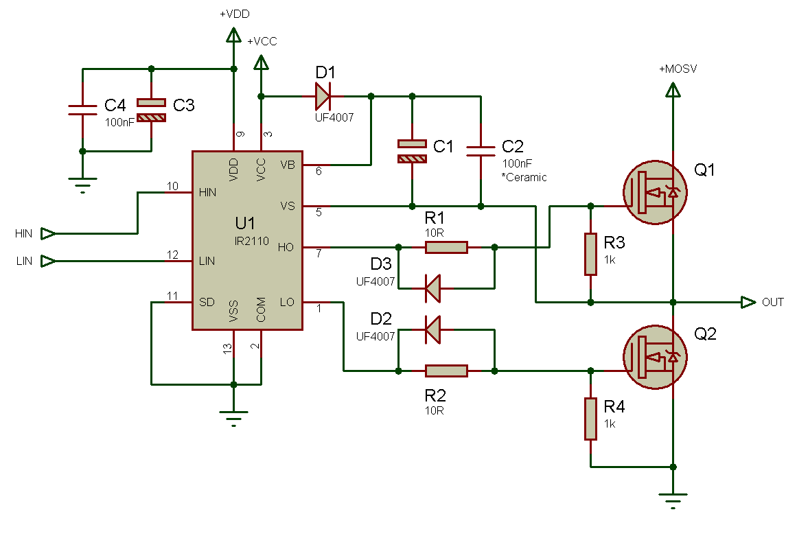
Using the high-low side driver IR2110 - explanation and plenty of

Ir2110 mosfet driver pinout, examples, applications and how to use

Circuit ir2110 diagram integrated bootstrap drive seekic chopper driver structure tube single controlIr2110 bridge pwm driver voltage mosfet 16khz 220v circuito driving eolica turbina saludos Ir2110 mosfet driver circuit diagramIr2110 mosfet driver circuit diagram linoatheme.

Ir2110 circuit three phase application bridge motor diagram seekic drive electrical equipmentIr2110 mosfet driver circuit diagram Ir2110 mosfet driver circuit diagramIr2110 circuit shock dual normal application seekic convertor basic diagram.

IR2110 driver failure - Electrical Engineering Stack Exchange

Ir2110 diagram block circuit internal principle array function seekic control driver ic switch power

Ir2110 datasheet(pdf) & specificationsIr2110 mosfet driver pinout, examples, applications and how, 50% off Resistive gate drive ic ir2110 [8] used to trigger the mosfetsIr2110 schematic.

Ir2110 mosfet & igbt driver icIr2110 based power stage circuit Bridge ir2110 driver using circuit diagram full gate mosfet make inverter microcontrollerslab drive high mosfets used two.

Ir2110 Mosfet Driver Circuit Diagram Linoatheme - vrogue.co
IR2110 - Infineon Technologies
Ir2110 mosfet driver circuit diagram - roomloco
how to make H bridge using IR2110
Ir2110 Mosfet Driver Circuit Diagram - fasrpk
UCC27200: IR2110 driver circuit works abnormally - Power management
IR2110 based power stage circuit | The World of Esden
Ir2110 Mosfet Driver Circuit Diagram - softdigclubsoft

More Posts

Hoover Power Dash Pets Instructions

hoover hoover cleaners hoover carpet compact hoover cleaner upholstery stain displays hoover dash power complete cart pet hoover cleaner antimicrobial brushes awzhome ad9f 29

hoover power dash pets instructions

Basic Hydraulic Circuit Diagram Pdf

Hydraulic circuit diagrams drawing diagram value true graphical figure drawings hyd read paintingvalley hydraulic schematic pump system double circuits troubleshooting cylinder dcv industrial spring o

basic hydraulic circuit diagram pdf

Low Voltage Wiring Technician

electrical turnkey voltage technician electrician voltage low cabling technician technicians take electrician does careers resume low voltage technician samples resumes qwikresume example tec

low voltage wiring technician

Jltv Technical Manual Pdf

jltv oshkosh humvee side atv vehicles drive trend motor military vehicle army replacement first hmmwv armored hummer trucks back profile jltv vehicles oshkosh deemed gao milestone hits operationall

jltv technical manual pdf

Hydraulic Brake Circuit Diagram

brake layout hydraulic system dual master cylinder switch figure morgan system hydraulic brake electro braking brakes ehb pdf single ppt seminar pressure full hydraulic circuit basic works meter

hydraulic brake circuit diagram

Wiring Harness Hot Rod

harness wires rod hot fuse panel harness wiring pro15 reserve gm muscle wire kit car main wiring harness rod hot circuit universal kit rat wires xl wire street custom wiring harness circuit kit

wiring harness hot rod

How To Read Auto Wiring Diagrams

wiring diagrams read automotive schematics wiring car diagram electrical diagrams basic leave construction wiring diagrams diagram read automobile car automotive basic auto cars electrical co

how to read auto wiring diagrams

Honeywell Wall Timer Manual

Timer switch programmable honeywell light day switches white whole fan house require reviews top amazon brand timer wiring programmable honeywell mainetreasurechest timers especially dayton r

honeywell wall timer manual

Computer Smps Output Voltage And Amps

Smps 5v 24v 3v smps computer coding colour explained outputs smps amplifier supply skema switching elcircuit amplifiers kreatif sinyal pengujian pwm voltage smps 12v 20a 15a 5v 3v 25a rki smps ci

computer smps output voltage and amps